- HOME
- SOLUTIONS
- PRODUCTS
-
 MFL+TFI Inspection Tool
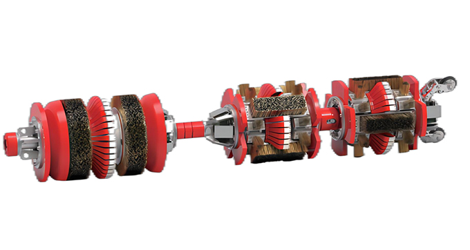
The MFL+TFl tool is composed of an axial excitation detection section and a circumferential excitation detectiorsection. Circumferential excitation detection magnetic field is distributed along the circumferential direction of the pipe wall, which can detect axial defect signals, and has strong detection ability for axial grooves. Axiaexcitation detection and circumferential excitation detection complement each other to realizeomni-directional detection.
READ MORE+
-
 Self-Propelled Caliper
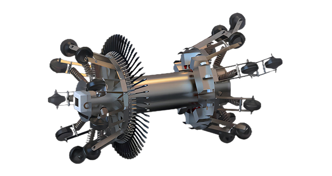
The self-propelled caliper can complete the detection work through autonomous crawling, which can imple-ment the geometric deformation detection and center-ine mapping before the new pipeline is put intoproduction, provide basic data for the new pipeline.
READ MORE+
-
 MFL
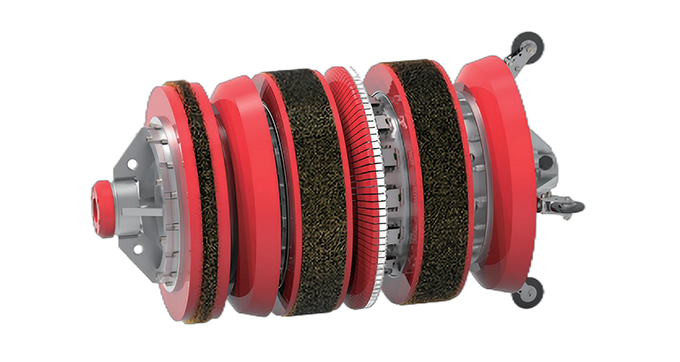
MFL
MFL can complete the detection of pipe defects, metal loss, pipe material changes, internal and external defectdiscrimination, pipe characteristics (pipe hoops, scar repair, bends, welds, tees, etc.), and provide comprehensive information of defect area, depth, orientation, location and so on.
READ MORE+
-
 Caliper
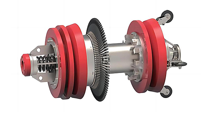
The caliper tool can detect the depression, ovalitydeformation, wall thickness change of the pipeline,and various pipeline accessories that cause the innerdiameter of the pipeline to change.
READ MORE+
-
- COMPANY
-
 ABOUT US
IP is a reliable company of pipeline inspection and data analysis with rich experience. Since its R&D in 1995, IP has provided the internationally leading technology to pipeline owners and operato...
READ MORE+
-
 CORE VALUES
IP has nearly 30 years of technology accumulation and industry experience. Based on this professional background, we have six core values that represent everyone in the IP company and the style of all...
READ MORE+
-
 QUALITY & HSE
At IP, we firmly believe that the strict Quality & HSE Management System can ensure the company to continue to provide high-quality products and services, and ensure the safety of the environment ...
READ MORE+
-
- NEWS
- CONTACT
 INTEGRITY SERVICES
 CORE SOLUTIONS